
Pneumatic valves are used to control compressed air flow to end-use devices and are fundamental building blocks for pneumatic systems.
A previous article provided an overview of typical pneumatic system components. Valves are a fundamental building block for these systems because they translate user or control system commands into compressed air flow to physically actuate field devices.
This article looks at some of the many options available when choosing pneumatic control valves. With a little research, designers will be able to find families of products to help them accomplish their pneumatic control goals comprehensively and consistently.
Pneumatic Control Valves vs. Process Valves
Valves come in all shapes and sizes. For the purposes of this article, we will be considering only pneumatic control valves. These valves are generally used to turn air pressure on or off in a pneumatic system to operate pneumatic devices downstream. Process valves, on the other hand, come in many configurations and are typically used to control the flow of process fluids or gasses.
Manual, Mechanical and Automatic Valves
Manually shifted pneumatic control valves are operated by a human usually via a handle or button. Mechanical valves may be configured as a position detector switch to supply air when triggered.
Solenoid valves are by far the more common type of automatic valve. Solenoid valves are operated with a control voltage, usually 24 Vdc or 120 Vac, that is applied to the electric solenoid coil. Pneumatic or air operated control valves are directly operated by a portion of the supply air pressure.
Control Air Pressure, Flow and Volume
It is important to coordinate pneumatic system pressure and flow according to component ratings and usage. End-use devices such as actuators need a specified pressure to operate, and these devices consume a specified volume of compressed air for every actuation based on their bore and stroke. Just as the usage requirements must be considered when sizing the air supply compressors, each pipe and valve along the way must be sized appropriately to provide the necessary pressure and flow downstream.
Shutoff, Dump Valves and Soft Startup
Compressed air is a source of energy for creating motive force on a machine. For safety, there must always be a way of shutting off or isolating this force. The simplest way is closing a main manual valve, but this can leave downstream equipment pressurized. A dump or relief valve is better for this purpose because it isolates the downstream pressure from the supply pressure and discharges any residual pressure. Many of these valves have red handles and lock holes so they can act as a safety lockout component. Careful designers also include soft startup valves so when air is first supplied to a machine the pressure gradually builds up to prevent damage or injury.
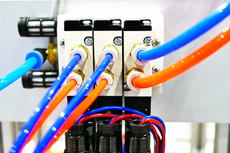
Valve Manifolds
Solenoid valves can be individual devices, or they can be ganged into manifolds for compactness, reduced plumbing and simplified installation. Common manifold valves are traditional electric-type, but there are also “smart” manifolds that can communicate to PLCs via industrial digital communication protocols, such as EtherNet/IP.
Control Valve Details and Options
Control valves are partially defined by their connection sizes, pressure ratings, airflow capacity and solenoid voltages. Some more details:
- Ports: Each air connection on a valve is a port. There are at least two, but there may be many more.
- 2-way vs. 3-way: A 2-way valve has two ports and is either open or closed. A 3-way valve has three ports, often referred to as A, B and C. When closed there is a path from A to B, while C is blocked; when open there is a path from A to C, while B is blocked. There are also more complicated combinations.
- Positions: Most valves have two or three positions. A popular valve style is 5-port 3-position. Solenoids can shift the valve to one side or the other, while upon de-energizing the valve spring returns to center.
- Single-acting coil vs. double-acting coil: Single-acting valves open when energized and spring closed when de-energized. Double-acting valves must be energized separately to shift to one position or another, and these types of valves remain in place when de-energized.
- Options: Indicator LED lights and integral surge suppression are useful solenoid options to help with troubleshooting and minimize failures.


