
Although today’s PLCs can do so much more, they still excel at their original purpose of executing discrete on/off logic.
The introduction of programmable logic controllers (PLCs) around the 1970s represented a huge leap forward for anyone tasked with industrial automation projects. At best, previous efforts relied on complex electrical design and wiring using switches, relays, timers and other more exotic devices such as drum sequencers. At worst, other complicated methods were still in use including pneumatic, hydraulic and mechanical assemblies such as drive shafts on machines.
 PLCs allowed control logic to be defined in software, instead of hardware. Not only were PLCs very compact compared to the thousands of relays they could replace, but the software logic was relatively forgiving to troubleshoot, and much simpler to change than hardwired systems. There was still wiring to field devices, but it went into and out of the PLC.
But just because PLCs are much more flexible than other hardware control options, it doesn’t mean they’re trivial to program. Becoming a PLC programmer, or in fact any type of programmer, is a special technical skill and usually requires training or advanced education. This post is intended to help new users understand some basic concepts behind PLC discrete programming, but it can’t replace the formal training and education required to become a skilled PLC programmer.
What Exactly Does “Discrete” Mean?
In the context of PLCs and industrial programming, the term “discrete” means a signal or logic that is only “on” or “off.” Discrete signals may have alternate representations such as 0=off=false=low and 1=on=true=high.
By comparison, analog means a signal or logic represented by a continuously variable number, such as temperature. Any analog value must have a defined engineering minimum and maximum value so the user and the PLC can understand the allowable operating range. Analog signals will be discussed in a future post.
PLC Inputs and Output
PLCs interact with the real world via inputs and outputs (I/O), which come in discrete and analog versions. Discrete inputs are received via wiring from on/off devices like selector switches, limit switches, proximity sensors and other sources. Discrete outputs are wired to drive lights, solenoids, relays and other devices to cause an action in the field, such as starting a motor. Of course, there are countless types of input and output devices, these are just a few common ones often used in industrial automation.
Data Types
Within a PLC, all the information is stored as data variables. Some PLCs have rigorous rules for I/O addressing and variable tagging. Newer PLCs allow more flexible tagging and numerous data types.
There are many atomic or basic PLC data types, but the most fundamental for handling discrete signals is a Boolean (BOOL) data type, sometimes called a bit. Many BOOLs can be packed together into larger data structures, such as a 16-bit WORD or integer (INT), but we will only consider individual BOOLs for the moment.
PLC Programming Languages
Since the original PLCs usually replaced electrical hardwiring, many PLC programming languages were created to look like the electrical control ladder diagrams everyone was already familiar with for performing on/off control. Therefore, a very popular PLC programming style or language, at least in North America, came to be known as ladder diagram (LD) graphical programming.
In recent years, a programming standard called IEC 61131-3 has become available to better define LD and other languages in a vendor-independent manner:
- Ladder diagram (LD), graphical
- Function block diagram (FBD), graphical
- Structured text (ST), textual
- Sequential function chart (SFC), for sequential and parallel control processing, graphical
Unfortunately, most brands of PLCs used their own specific I/O addressing, variable naming and graphical programming styles. This means programs are not easily portable among brands, or sometimes among a single vendor’s product lines.
Due to these issues, another improvement called CODESYS has reached the industrial automation world. This is an IEC 61131-3 programming environment enabling users to perform vendor-independent PLC development to some extent, but not without additional effort to ensure compatibility.
All of these languages can be used for discrete programming, but we will focus on only LD. LD logic is scanned top-to-bottom, left-to-right. PLC logic scans over and over, very quickly and reliably, and has a special provision called a watchdog timer that will act if a fault is sensed
The left vertical rail can be thought of as energized power in a hardwired circuit. Each horizontal rung contains contacts which may open or close to stop or pass power to the output coils on the right.
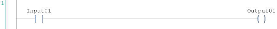
In this basic diagram, assume Input01 is wired in from a selector switch, and Output01 is wired out to a light. During execution of PLC runtime logic, if the switch is turned on in the field, then Input01 contact closes and energizes Output01, which in then turns on the field light.
PLC Program Building Blocks
The preceding example is simplistic but represents a building block showing how PLC discrete programming can monitor inputs, execute logic and command outputs. Based on this principle, complex systems can be automated. Users with electrical knowledge may find it easier to learn LD, but general programming skills are also important. Once LD is mastered, it can be applied to many types of PLCs. Vendors offer paid classes and free online training, and many also provide videos and other training aids.


