Good industrial control panel grounding practices can be easily applied to improve safety and performance, but are often overlooked, leading to problems.
Proper grounding for industrial automation systems is a crucial element for providing safety, uptime and performance. Yet within industrial control panels, it’s all too easy to forget grounding elements, or to install them improperly. In most cases, the control panel will function normally with improper grounding, but will cause a hazard if and when a fault occurs.
The NFPA 70 (NEC) Article 250 discusses “Grounding and Bonding” with a focus on how an overall grounding system at an installation site is achieved, usually with grounding electrodes installed into the earth. For details on grounding within control panels, NFPA 79 and UL508A provide the required details.
Control panels generally have an incoming power feed with a grounding conductor, which in turn is bonded to the enclosure. This post looks at some common industrial control panel grounding and bonding practices.
Safety First
From a safety standpoint, a control panel enclosure must be positively and properly grounded in order to clear any electrical faults. The ground path resistance from the enclosure back to the source ground must be very low so if any energized conductor contacts the enclosure, the resulting fault current has a low-impedance path to safely conduct to ground. This allows the overcurrent components to positively and quickly open and de-energize the circuit to remove the source of power.
Poorly grounded or ungrounded enclosures will not clear a fault as quickly, if at all, and thus can remain operating and energized, possibly causing an enclosure to carry a non-zero voltage. Personnel working in or around this type of enclosure may receive an electrical shock from this floating voltage.
Minimizing Noise
The NEC is focused on preventing fires and electrical hazards and is not specifically concerned with the electrical noise that may impact modern control systems using digital devices and low voltage analog signals. Good grounding practices will help attenuate any electrical noise, such as that generated by variable frequency drives. Less noise leads to less chance of problems with sensitive equipment.
Grounding Hardware
Electrical connector hardware for grounding should be listed for the purpose, and for a UL 508A listed assembly all fittings must comply with that rating. Some typical termination means for ground wires are:
- Grounding lug: This fitting has a compression portion for receiving the incoming wire, and a hole allowing it to be bolted to a suitable enclosure or backpanel stud.
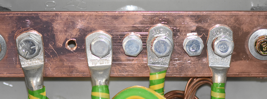
- Grounding bar: This is a bar that can accept many ground conductors, and it’s usually bonded to the backpanel.
- Grounding terminal: This is a compression terminal block, usually colored green or green/yellow, that grounds to the backpanel or DIN rail when installed.
Grounding Enclosures and Backpanels
Control panel enclosures are often metal, and usually feature an internal metal backpanel for mounting devices. Even non-metallic enclosures usually have a metal backpanel. A UL-listed enclosure will come with documentation which must be followed, and with hardware which must be used to ground all metal elements of an enclosure. This may include specific ground symbol stickers to be placed at each connection point.
Usually the incoming ground is landed on a backpanel-mounted grounding lug, bar or terminal. This connector bonds the ground conductor to the backpanel. Backpanels are installed with nuts or machine screws and star washers to ensure they are bonded to the metal enclosure. Metal doors, whether continuous-hinge type or removeable-hinge, need a separate bonding jumper from the enclosure or backpanel to the door, and are usually provided with studs for this purpose.
Even when star washers are used, it is always recommended that grounding connections made at painted surfaces have the paint carefully ground down to bare metal for the best connection. Also, when DIN rail is installed to a backpanel, drilled and tapped machine screws should be used to make a bonded connection.

Grounding Conductors
Grounding conductors must be sized per the NEC based on the size of the overcurrent device protecting the circuit. The color of insulated ground conductors is green or green with a yellow stripe, per NFPA 79. However, there are cases where bare conductors or braided straps may be acceptable, such as where flexibility is needed. Grounding points may be identified with a symbol or the terminology potential earth (PE).
Star Grounding
Grounding connections should never be performed as a series of consecutive jumpers or in a “daisy-chaining” style, because any one failed connection would remove the ground connection from all the downstream devices. Instead, a “star” design should be used where each ground has a home-run connection to the main grounding bar.
Grounding PLCs, VFDs, Power Supplies and Devices
Common devices used in control panels will often have their own special grounding requirements. Installation manuals for PLCs, variable frequency drives, power supplies and the like must be carefully followed because sometimes the grounding requirements are more restrictive, such as requiring oversized conductors, than would otherwise be needed.
Chassis Ground and Isolated Ground
Sometimes the term “chassis ground” is used to describe a grounded enclosure. Product vendors occasionally call for an “isolated ground,” but most control panels should not have their own completely separate grounding system installed. A properly installed star grounding system provides a safe and reliable control panel installation.


The picture you have next to the “Grounding Hardware” that has the following comment: Electrical yellow green ground wires is connected to ground copper bar or earth bonding bar in metal electric breaker box with electrical circuit breakers and electrical grounding sign near ground bolt inside box.
Do you have the manufacture name and part number of the Ground Copper Bar, i see its a DIN rail mount 13 pole item.
Thanks
Hi Alex, the images we used on the Industrial Control article is an example of a grounded bar and not our actual inventory so I do not have the information on that exact one. We do, however, carry the following Ground Copper Bar – https://www.alliedelec.com/product/hoffman/dg19/70067058/. If you need more information or are interested in a quote, please reach out to us at (866) 433-5722 or email us at customer.service@alliedelec.com.